If you have been running a WISP for a while, you are probably used to throwing up three or four wide sectors, each blasting a big 90° or 120° slice of coverage, and calling it a day. For fixed wireless, that works fine. Your CPEs stay put, handovers are non-existent, and big beams keep the map looking “full.”
LTE, especially in TDD bands like CBRS, is a different animal. The same wide-beam layout that is fine for fixed wireless can create interference headaches, messy handovers, and wasted spectrum in LTE. In the mobile world, precision matters more than simply painting the map green.
The WISP to LTE Leap Gone Wrong
Picture this: you upgrade a rural WISP site to LTE but keep the same four wide-beam panels you have used for years. On paper, the coverage maps look great with no gaps and no obvious holes.
Two weeks in, the calls start coming. Mobile VoIP users get dropped mid-sentence. Some devices cling to a weak sector instead of handing over, only to collapse entirely. Data speeds swing wildly.
The problem is not the radios. It is the sectoring strategy.
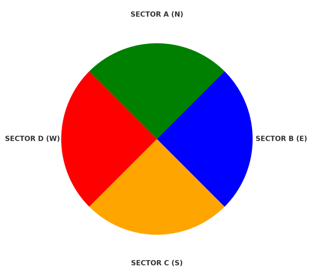
Traditional LTE 3 Sector Deployment
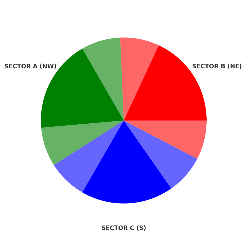
Traditional WISP 4 Sector Deployment
Why Three Sectors Are the LTE “Gold Standard”
A three-sector LTE site splits the area into roughly 120° slices. This is the balance point where coverage, interference control, and capacity all work together.
- Load Balancing: Each sector gets its own radio resources, so devices are spread evenly instead of piling onto one panel.
- PCI Management: LTE only has 504 Physical Cell IDs. Every extra sector uses more IDs and adds neighbor relationships, making it harder to avoid collisions.
- Mobility Stability: Smaller, cleaner neighbor lists mean faster and more reliable handovers.
Why 65° Beats 120° in LTE
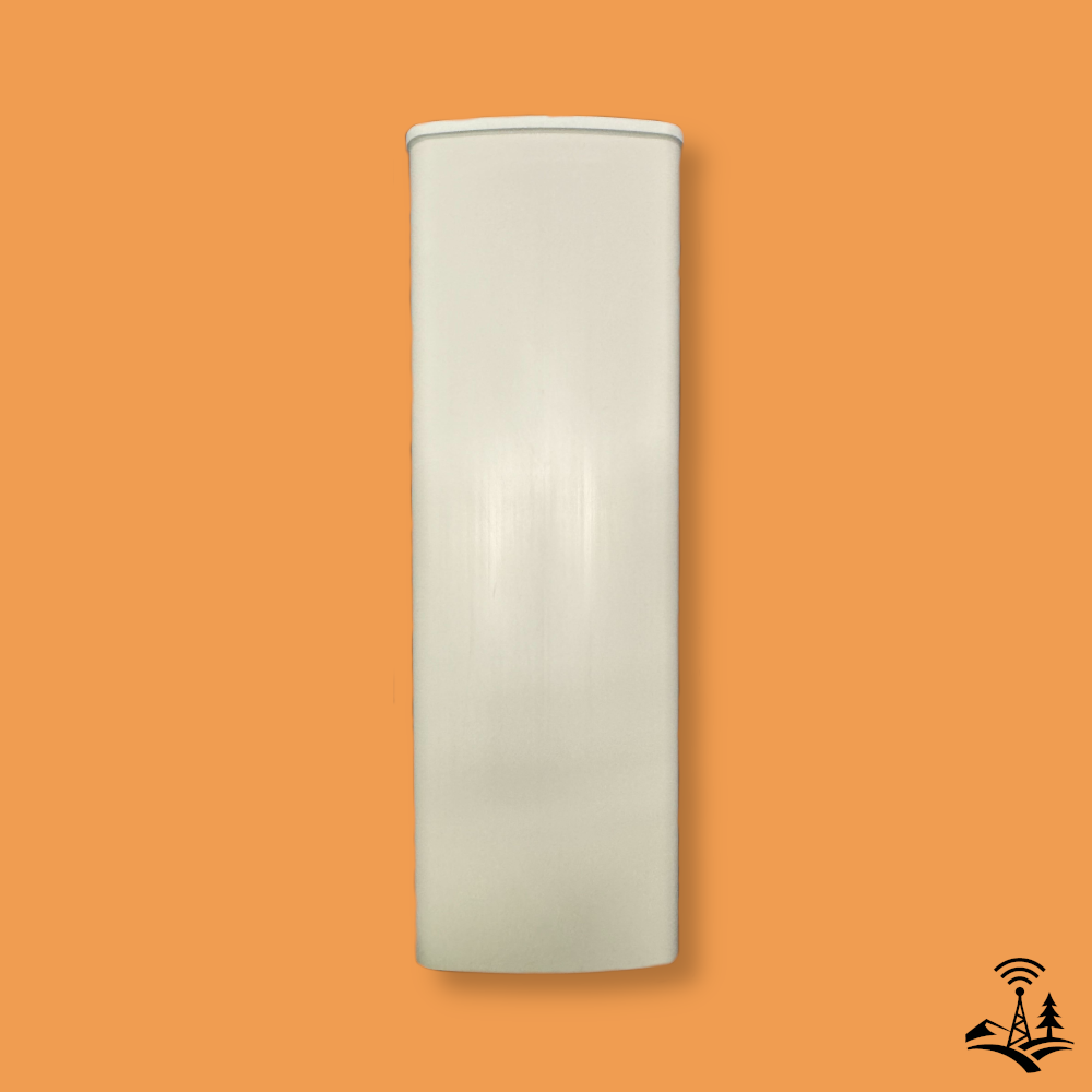
Pictured Above: Alpha Wireless AW3161-M-F 65° Sector Antenna (RET support)
Instead of wide 120° panels, LTE operators use antennas with about 65° horizontal beamwidth. Narrower beams act like a spotlight instead of a floodlight, more focused, brighter, and cleaner at the edges.
- Cleaner Frequency Reuse: Main lobes meet precisely, making aggressive reuse patterns possible without interference chaos.
- Higher Gain: A tighter beam pushes a stronger signal to the UE without increasing transmit power.
- Less Overlap: Narrow beams reduce “ping-pong” handovers between sectors.
The Question of Coverage Gaps
This is a common concern for WISP operators moving to LTE. At first glance, three 65° beams appear to leave slices between sectors where signal strength is noticeably lower. These are often called “null zones.”
LTE does not collapse the moment you step outside the -85 dBm comfort zone. Even in these lower-signal areas, UEs can maintain solid connections.
- Reduced Self-Interference: By narrowing the beam, you cut down on overlapping signals from adjacent sectors. A cleaner RF environment means the UE can decode data more reliably even at lower received power.
- LTE’s Interference Handling: LTE modulation, coding, and HARQ (Hybrid Automatic Repeat Request) allow the network to keep throughput high and latency low even when RSRP drops, provided the SINR remains strong.
- Null Zone Reality: The “gap” is not a dead zone. It is more like a dimmer patch of light. With less self-noise, these areas often outperform the edge of a wide-beam sector in capacity and latency.
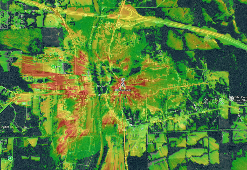
Pictured Above: 3 Sector Coverage Area, 3 Sectors, 65 degree sectors in Centreville, Alabama. Generated with cnHeat(tm), a coverage map generation tool developed by Cambium Networks.
While this article is focused on delivery of an even 360 degrees of coverage, not every situation calls for that. Sometimes, dual 30 degree sectors for example makes more sense, like when the tower site is up against the national forest with nothing to cover in the northern azimuth, as we saw on our tower in Eoline, Alabama. Michael Halls, LTE Expert from Nimbus Solutions, had this to say:
“Antenna deployment is never one size fits all. The key is to use the antenna that fits the application. If an omni makes sense, use an omni. The bigger question every LTE operator should ask is: do I want weak coverage over a broad area or high quality signal in a specific area? LTE has a full spectrum of uses and your sectoring strategy should match the goal of the transmission.”
— Michael Halls, LTE Expert, Nimbus Solutions
CBRS, TDD, and Why Precision Matters
CBRS runs in Time Division Duplex (TDD), where uplink and downlink share the same channel but at different times. If one site’s downlink bleeds into another’s uplink, you have cross-link interference, which is the LTE equivalent of two people talking over each other on a walkie-talkie.
Three well-aimed 65° beams help contain interference and keep TDD synchronization clean, making frequency reuse patterns such as Reuse 1 or Reuse 3 work without self-sabotage.
The Four-Sector Temptation
Four-sector designs can add capacity in certain situations but at a cost: more PCIs to manage, more neighbor relationships to track, and more interference potential. Unless a site is engineered from the start for four-sector LTE, three sectors will often outperform it.
Real-World Contrast
- Site A: Four 90° panels from the WISP days, running LTE in CBRS. It looks full on the map but suffers from interference, bouncy handovers, and unpredictable speeds.
- Site B: Three 65° sectors, well-aimed, PCI plan tight, TDD synchronized. No practical coverage holes, smoother mobility, more predictable capacity.
Takeaway
If you are coming from fixed wireless, moving to LTE means rethinking what good coverage looks like. The goal is not just to light up every square inch with high RSRP. It is to deliver consistent capacity, low latency, and stable handovers across the footprint.
Three sectors, 65° beams, and proper PCI and TDD coordination form the foundation for LTE and CBRS site performance. This is not just a rule of thumb. It is the proven formula that works in the real world.
We sell certified refurbished three-sector Nokia AZQC sites that are ready to deliver 360 degrees of coverage while following LTE best practices. Click here to learn more.